Worms & Worm Shafts

Download
View all downloads

Description

Custom Worms & Worm Shafts

Custom Worms & Worm Shafts for Compact Right-Angle Drives

A worm shaft—also called a worm screw or worm gear shaft—is not simply a threaded shaft. It works as one half of a matched gear set, where the worm profile, axial module, number of starts, lead angle, hand and mating-wheel geometry must agree before the drive can run smoothly.

YUBAO manufactures drawing-based worms and worm shafts for reducers, actuators, automation, material-handling equipment and other OEM drive assemblies. Turning, worm-profile machining, heat treatment, grinding and inspection are planned around the finished mesh, shaft datums and production volume—not around a generic catalogue part.

Axial Module 0.5–4.0Drawing-review range
1–4 StartsStandard review range
Ø6–Ø30 mmPitch diameter reference
DIN/ISO Grade 6Reference accuracy grade
Send a Worm Shaft Drawing

Reference values support early drawing review. Final mesh geometry, material, heat treatment, surface condition and inspection scope are confirmed against the released drawing and mating-wheel data.

Custom worm shaft and worm wheel set on a transparent background
Custom Worm & Worm Shaft Range ZA · ZI · ZK · ZC · ZT · 1–4 starts · matched wheel review
Why Worm Drives

Treat the Worm and Wheel as One Working System

A worm drive earns its place when ratio, packaging and controlled motion matter at the same time. The worm profile cannot be reviewed in isolation: the mating wheel, centre distance, bearings, lubrication and shaft datums all influence how the set carries load, generates heat and wears.

01

Put ratio, lead and centre distance on the same drawing

Module, start count, pitch diameter, lead angle, hand, wheel tooth count and centre distance define the mesh together. Reviewing them as one system helps prevent contact and backlash problems.

02

Control sliding contact, not just tooth shape

Worm gearing carries substantial sliding contact. Surface finish, hardness, material pairing, lubrication and alignment directly affect heat, wear, noise and service life.

03

Build the shaft around bearings, seals and the mating wheel

Journals, shoulders, threads, keyways and locating faces are machined and inspected from the functional datum plan so the worm mesh remains related to the housing and bearings.

Technical Parameters

Worm & Worm Shaft Capability at a Glance

Reference ranges for early project screening. Final capability depends on worm profile, module, starts, mating-wheel geometry, material, heat treatment, duty cycle and the functional datum plan.

Feature Reference Capability Engineering Relevance
Profile & Mesh ZA, ZI, ZK, ZC and ZT profiles · standard pressure angle 20° · special profiles reviewed by drawing The worm profile, wheel geometry, hand and centre distance must be reviewed as one meshing system.
Module & Starts Axial module mx 0.5–4.0 mm · 1–4 starts as the standard review range Module and start count affect ratio, lead angle, contact behaviour, tooling and manufacturing route.
Pitch & Ratio Data Worm pitch diameter d1 Ø6–Ø30 mm · mating-wheel tooth count and ratio drawing-defined Pitch diameter, wheel tooth count and centre distance are checked together before production.
Accuracy & Surface DIN/ISO Grade 6 reference · tooth Ra 0.8 μm · Fr ≤0.02 mm (20 μm) reference Final runout and surface requirements depend on diameter, accuracy grade, heat treatment, datum and inspection method.
Material & Treatment HRC 58–62 reference after compatible treatment · material pairing and lubrication application-defined Hardness, finish and material pairing are selected around sliding contact, heat, wear, load and service life.
Additional Technical Data

Open a group only when the drawing needs a deeper review of mesh geometry, accuracy, surface condition or inspection.

Worm Geometry & Mesh Details
Item Reference Information Why It Matters
Worm Profile Type ZA, ZI, ZK, ZC, ZT or drawing-defined Profile type governs tooth geometry, tooling and inspection.
Axial Module mx 0.5–4.0 mm reference range The worm and wheel must use compatible module data.
Number of Starts z1 1–4 as the standard review range Start count affects ratio, lead angle, sliding speed and efficiency.
Pitch Diameter d1 Ø6–Ø30 mm reference Pitch diameter works with module and starts to define the mesh.
Pressure Angle 20° standard reference; selected special profiles reviewed The pressure angle must agree with the mating wheel.
Hand & Lead Angle Left- or right-hand; drawing-defined lead angle Hand and lead direction must match the required wheel and rotation.
Mating Wheel Tooth count, centre distance, backlash and material drawing-defined Supplying both drawings allows the contact relationship to be reviewed before tooling.
Accuracy, Surface & Inspection
Item Reference Information Why It Matters
Precision Grade DIN/ISO Grade 6 reference; project requirements may fall within DIN 5–7 The released grade must identify the standard and inspection method.
Tooth Roughness Ra 0.8 μm reference; typically 0.4–0.8 μm where finishing is specified Surface condition influences friction, heat, noise and wear.
Tooth Hardness HRC 58–62 reference after compatible heat treatment Hardness must be planned with material, case depth, distortion and final finishing.
Pitch-Diameter Runout Fr ≤0.02 mm (20 μm) reference Final tolerance depends on pitch diameter, module, grade, datum and measurement method.
Shaft Datums Journals, shoulders, threads and locating faces drawing-defined Mesh position must remain related to the bearings and housing.
Inspection Profile, module, starts, hand, lead, runout, roughness, hardness and shaft geometry The inspection plan follows application risk and repeat-production requirements.
Design Relationships Used During Drawing Review
Item Reference Information Why It Matters
Diameter Quotient q = d1 / mx Checks the relationship between worm pitch diameter and axial module.
Lead Angle tan γ = z1 / q Links start count and diameter quotient to the lead angle.
Lead pz = z1 × π × mx Defines axial advance for one worm revolution.
Axial Pitch px = π × mx Checks the pitch relationship used by the worm profile.
Manufacturing & Inspection

From Worm Geometry to an Assembly-Ready Shaft

The route changes with profile type, module, material, hardness, quantity and the worm’s position relative to the bearing journals. Machining, heat treatment, finishing and inspection are planned as one sequence.

CNC turning and worm profile machining for a custom worm shaft
Worm Manufacturing

Machine the profile around the finished mesh

Material preparation and CNC turning establish the journals, shoulders and locating faces. The worm profile is then milled, hobbed or otherwise generated according to the selected profile, module and starts. Heat treatment and tooth finishing are added only where the drawing and duty cycle require them.

Material preparation · CNC turning · worm-profile machining · heat treatment · tooth grinding or polishing
Worm profile, lead and shaft runout inspection
Finishing & Inspection

Inspect the features that control the mesh

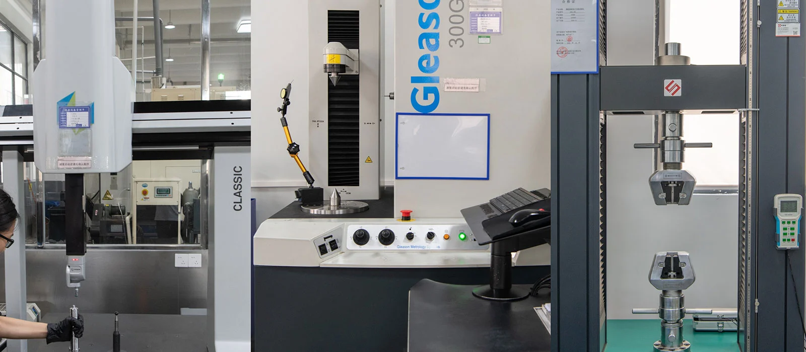
A worm can meet its individual dimensions and still perform poorly if lead, runout or shaft datums do not agree with the wheel. Inspection therefore checks profile, module, starts, hand, lead, pitch diameter and surface condition together with the journals and locating faces used in the gearbox assembly.

Profile verification · lead and hand checks · radial runout · roughness · hardness · journal and datum inspection
Typical Applications

Where Custom Worms & Worm Shafts Work

YUBAO reviews the worm, mating wheel and shaft features around the ratio, load, speed, lubrication and assembly shown in the drawing.

worm reducer and compact right-angle drive application
01

Reducers & Compact Right-Angle Drives

Custom worm sets for gearboxes that need a high reduction ratio, smooth motion and a compact 90-degree shaft arrangement.

servo actuator and automation application using a custom worm shaft
02

Servo Actuators & Automation Equipment

Worm shafts for positioning, indexing, clamping and adjustment mechanisms where controlled movement and limited space matter.

material handling and lifting application using a custom worm shaft
03

Material Handling & Lifting Systems

Drive components for hoists, conveyors, platforms and handling equipment requiring torque multiplication and dependable low-speed output.

pump valve and special machinery application using a custom worm shaft
04

Pumps, Valves & Special Machinery

Drawing-based worm shafts for valve operators, pump drives and special mechanisms with application-specific journals, threads or keyways.

FAQ

Before You Send a Worm or Worm Shaft Drawing

Can YUBAO manufacture worms and worm shafts directly from customer drawings?

Yes. YUBAO reviews the worm profile, module, starts, hand, lead angle, material, heat treatment, shaft datums, mating-wheel information and expected volume before confirming the manufacturing route.

Which worm profiles can YUBAO review?

Drawing-based ZA, ZI, ZK, ZC and ZT profiles can be reviewed. Final feasibility depends on module, pitch diameter, start count, pressure angle, tooling access and inspection requirements.

Can YUBAO review the worm and mating worm wheel as a set?

Yes. Supplying both drawings is the best way to confirm ratio, centre distance, hand, contact relationship, backlash target and material pairing before production.

What information helps YUBAO prepare a useful quotation?

Send the finished-part drawing or 3D model, worm profile type, axial module, start count, hand, pressure angle, mating-wheel tooth count, centre distance, material, heat treatment, roughness, accuracy grade, annual volume and application information.