
01
Put several functions into one finished shaft
Bearing journals, shoulders, flats, keyways, threaded ends and retaining features can be combined in one drawing-based component, reducing the need for collars, adapters or separate locating parts.
A custom machined shaft, sometimes described as a non-standard shaft, is built around a specific assembly. Steps, shoulders, flats, keyways, threads and relief grooves each have a job—locating a bearing, carrying torque, locking a hub, guiding a coupling or setting an axial position.
YUBAO manufactures made-to-print shafts for motors, reducers, industrial automation, material handling and special equipment. Send the finished drawing or 3D model, and our team will review the geometry, material, heat treatment, annual volume and inspection requirements before selecting the machining route.
Reference values support early drawing review. Final tolerances are confirmed feature by feature after geometry, material, heat treatment and inspection access are reviewed.

A non-standard shaft earns its place when several functions need to stay related on one axis. The geometry should simplify the assembly without creating unnecessary machining, weak transitions or difficult inspection conditions.
Bearing journals, shoulders, flats, keyways, threaded ends and retaining features can be combined in one drawing-based component, reducing the need for collars, adapters or separate locating parts.
Coaxiality, symmetry, end distance, runout and surface finish are reviewed as one datum structure so each flat, keyway, thread and journal works with the mating assembly.
Turning creates the stepped diameters, milling produces flats and keyways, threading forms retaining features, and grinding finishes journals and fit surfaces where tighter control is required.
Two or more diameters locate bearings, gears, seals, couplings and spacers. Shoulder positions, transition radii, relief grooves and section-to-section coaxiality determine how the shaft assembles and runs.
A machined flat can provide anti-rotation, wrench access, clamping or sensor positioning. Width, length, depth, symmetry and end position must work without weakening the local section unnecessarily.
Keyways create a positive torque connection to a hub, gear, sprocket or coupling. Type, width, depth, length, symmetry and axial position must match the mating component.
External threads retain bearings, adjust axial position or secure a mating component. Thread form, pitch, fit class, hand, effective length, coaxiality and relief details are reviewed together.
The ranges below support early drawing review. Final capability depends on shaft length, diameter changes, material, heat treatment, tool access, datum structure and inspection method.
| Feature | Reference Capability | Engineering Relevance |
|---|---|---|
| Stepped Geometry | Ø2.53–300 mm · drawing-defined sections · R0.2 mm minimum transition reference · relief width 0.5–4.0 mm | Diameter changes, shoulders, radii and relief grooves are assigned from the finished-part datum structure and load path. |
| Milled Flats | Width 2–200 mm · length up to 500 mm · depth up to 50 mm · h9–h11 reference | Flat size, symmetry and end position are reviewed against anti-rotation, clamping, wrench access and local section strength. |
| Keyways | Width 2–30 mm · depth up to 16 mm · length up to 500 mm · P9 / Js9 reference · Type A / B / C | Keyway geometry must match the mating key, hub, torque load, cutter access and shaft-centerline relationship. |
| External Threads | Standard, trapezoidal and drawing-defined forms · pitch 0.3–4.0 mm · effective length 3–100 mm · Grade 6 reference | Thread form, hand, fit, end position, coaxiality and relief groove are selected around the mating part and assembly function. |
| Accuracy & Finishing | Section coaxiality down to 0.01 mm · flat/keyway symmetry 0.05 mm · thread coaxiality 0.05 mm · grinding and heat treatment available | Final values depend on shaft proportions, treatment movement, functional datums, grinding access and inspection method. |
Open a group only when the drawing needs a deeper review of a specific shaft structure or inspection relationship.
| Control Item | Reference Capability | Engineering Note |
|---|---|---|
| Step Count | Drawing-defined | The number of sections follows the bearing, gear, seal, coupling and retention layout. |
| Maximum Diameter | Ø300 mm | Overall feasibility depends on total length, section proportions, material and machining access. |
| Minimum Diameter | Ø2.53 mm | Small sections require review of stiffness, tool access, heat treatment and handling risk. |
| Section Dimensions | D1×L1, D2×L2 and drawing-defined sequences | Each diameter and length is assigned from the finished-part drawing. |
| Transition Radius | R0.2 mm minimum reference | Radii should be selected around fatigue, stress concentration, bearing clearance and grinding access. |
| Grinding Relief Groove | Width 0.5–4.0 mm · bottom diameter drawing-defined | The groove must clear the grinding wheel without weakening the shoulder unnecessarily. |
| Section Coaxiality | Down to 0.01 mm | The controlled sections and datum axis must be identified in the drawing. |
| Feature | Reference Capability | Project Note |
|---|---|---|
| Flat Width | 2–200 mm · h9–h11 reference | Selected around clamping, wrench access, sensor positioning or anti-rotation requirements. |
| Flat Length & Depth | Length up to 500 mm · depth up to 50 mm | Depth must be checked against remaining section strength and local stress. |
| Flat Symmetry & Position | Symmetry down to 0.05 mm · start position ±0.1 mm reference | Referenced to the shaft centerline, end face or drawing-defined datum. |
| Flat Surface Finish | Down to Ra 1.6 μm | Applied where clamping, contact or locating performance requires it. |
| Keyway Width | 2–30 mm · P9 / Js9 reference | Must match the selected key and hub fit. |
| Keyway Depth & Length | Depth up to 16 mm · +0.2 mm reference where applicable · length up to 500 mm | Depth, effective length and cutter runout should be shown in the drawing. |
| Keyway Type | Type A, Type B or Type C | Type selection depends on end condition, cutter access and assembly method. |
| Keyway Symmetry & Finish | Symmetry down to 0.05 mm · surface finish down to Ra 3.2 μm | Critical when the keyway must remain centered to journals or other torque features. |
| Thread Item | Reference Capability | Engineering Note |
|---|---|---|
| Thread Types | Standard, trapezoidal and drawing-defined rectangular forms | The selected form must match the nut, adjustment function and load direction. |
| Typical Designations | M20, Tr30×6 or drawing-defined | Final designation follows the drawing and applicable thread standard. |
| Pitch Range | 0.3–4.0 mm for standard thread review | Coarse or fine pitch is selected around diameter, load, adjustment and retention requirements. |
| Effective Thread Length | 3–100 mm | The working length should exclude runout and relief zones. |
| Thread Accuracy | Grade 6 reference · 6g / 6H where applicable | The fit class must match the mating thread and selected standard. |
| Thread Hand | Right-hand or left-hand | Confirmed from the rotation direction and assembly function. |
| Surface Finish | Down to Ra 1.6 μm | Applied where friction, adjustment or sealing behavior requires it. |
| Thread Coaxiality | Down to 0.05 mm relative to the reference OD | Important for nuts, bearing retention and rotating assemblies. |
| Runout & Relief | Drawing-defined from pitch and mating requirement | The thread end, relief width, bottom diameter and axial start position should be specified. |
The process route is built around the features that must stay related after machining, heat treatment and grinding.

CNC turning establishes the stepped diameters, shoulders and outside references. Milling creates flats and keyways, thread machining adds retaining or adjustment features, and grinding finishes the journals and fits that require tighter control.
Inspection checks the relationships between journals, shoulders, flats, keyways and threads. Width, depth, symmetry, axial position, runout, coaxiality and surface finish are tied to the agreed functional datums.
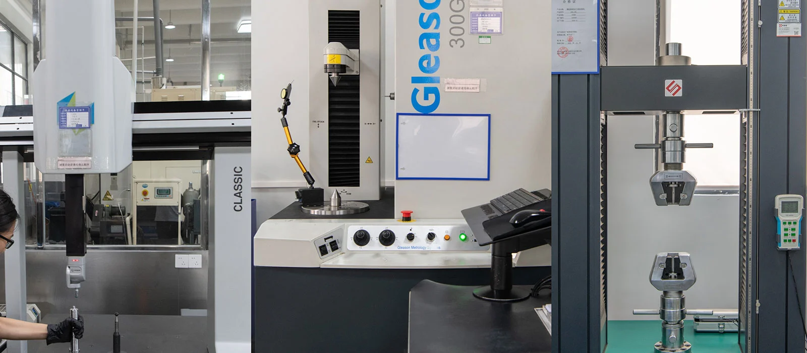
YUBAO matches the shaft geometry, material, treatment and inspection plan to the load, fit and assembly shown in the drawing.

Stepped journals, keyed connections and threaded retaining ends where bearing location, torque transfer and repeatable fit must work together.

Drawing-based shafts with flats, shoulders, threads and precision journals for positioning, clamping, actuator and spindle assemblies.

Custom shafts for conveyors, lifting systems, pump drives and compact machinery that need keyed hubs, stepped load zones or threaded retention.
Another shaft route may suit the drawing better when torque transfer, weight, material use or assembly access changes.


