Description

Custom Hollow Shafts

Hollow Shafts for Precision Drive Systems

A hollow shaft only works when the bore and outside features are treated as one part. Wall thickness, journals, shoulders, keyways and datum relationships all affect stiffness, runout and fit.

YUBAO manufactures made-to-print hollow shafts for servo motors, industrial automation, reducers, electric drive assemblies and machine tools. Depending on the drawing, the route may include deep-hole drilling, boring, broaching, internal grinding and outside-diameter grinding, followed by coaxiality and runout inspection.

Ø21–350 mmOutside diameter capability range
Ø10–180 mmInner bore diameter range
≤1500 mmOverall shaft length by drawing
≤0.03 mmInner-to-outer coaxiality target
Send a Hollow Shaft Drawing

Capability values are project-dependent. Final tolerances, material, heat treatment and inspection scope are confirmed after drawing review.

Custom precision hollow shafts manufactured by YUBAO
Custom Hollow Shaft Range Drawing-based geometry · bore · journals · keyways · shoulders
Why Hollow Shafts

A Bore Should Add Function, Not Just Remove Weight

Hollow construction can reduce rotating mass, create a passage for cables or fluids, or provide an internal fit. The benefit depends on keeping enough wall thickness and controlling the bore to the same datum structure as the outside features.

01

Lower inertia where response matters

Removing material near the center can reduce rotating mass while journals, seals and torque-transfer features stay where the assembly needs them.

02

Space for routing and assembly

Through, blind and stepped bores can carry wiring, coolant, drawbars or locating features without adding an external passage.

03

One functional datum relationship

The bore, wall thickness, shoulders and bearing seats are reviewed together because runout and fit depend on how those features relate.

Technical Parameters

Hollow Shaft Capability at a Glance

Reference ranges for early project screening. Final feasibility depends on the bore type, bore depth, wall thickness, material, heat treatment, datum structure and inspection access defined in the drawing.

Feature Reference Capability Engineering Relevance
Size & Bore Range OD Ø21–350 mm · ID Ø10–180 mm · finished length up to 1500 mm Early screening depends on bore depth, wall thickness, length-to-diameter ratio, section changes and machining access.
Bore Types & Internal Features Through, blind, stepped and drawing-defined special bores · keyways and selected internal splines The route changes with tool access, bore depth, feature position, chip removal and inspection access.
Accuracy & Datums Straightness down to 0.01 mm · cylindricity 0.005 mm · radial runout 0.008 mm · inner-to-outer coaxiality 0.03 mm Final values must be tied to the functional datum plan, finished length, wall uniformity and heat-treatment movement.
Surface & Fit OD Ra 0.2–0.8 μm · ID Ra 0.8–3.2 μm · H7–H9 fit bores where geometry allows Finish and fit are assigned only to bearing, sealing, locating, fluid-routing or precision assembly interfaces.
Materials & Process 20CrMnTi, 40Cr, 42CrMo and drawing-defined steels · deep-hole drilling, boring, broaching, internal and OD grinding The practical route depends on load, fatigue, wear, bore geometry, annual volume, heat treatment and inspection requirements.
Additional Technical Data

Open a group only when the drawing needs a deeper review of bore access, wall design, precision finishing or inspection.

Bore Geometry, Access & Machining Details
Review Item Reference Capability Engineering Note
Bore Type Through, blind, stepped and drawing-defined special bores Process selection depends on bore depth, entry access, internal steps and the required finished surface.
Deep-Hole Drilling Bore Ø10–80 mm · L/D up to 20:1 reference Actual depth depends on diameter, stock condition, straightness requirement and drill access.
Boring Bore Ø50–180 mm · H7 reference where feasible Used where the bore is accessible and the required diameter, fit and surface can be reached by boring.
Fit-Bore Tolerance H7–H9 where specified and feasible The tolerance must be reviewed against bore depth, diameter, material, treatment and finishing access.
Internal Keyways 5–22 mm reference · JS9 where applicable Broaching or secondary machining depends on bore size, keyway position, through-access and inspection method.
Wall Thickness & Bore Ratio Drawing-defined Wall thickness should be verified against torque, speed, torsional stiffness, fatigue, heat-treatment movement and local stress concentration rather than a weight target alone.
Accuracy, Finish, Material & Inspection
Control Item Reference Capability Project Note
Straightness Down to 0.01 mm The requirement must be tied to finished length, diameter and the agreed measurement span.
Cylindricity Down to 0.005 mm Applied only to agreed outside, inside, journal or fit surfaces.
Radial Runout Down to 0.008 mm The reference centers, datum axis and measured feature must be identified in the drawing.
Inner-to-Outer Coaxiality Down to 0.03 mm Important for wall uniformity, rotating stability, fit and repeatable assembly.
Surface Finish OD Ra 0.2–0.8 μm · ID Ra 0.8–3.2 μm · internal grinding down to Ra 0.4 μm where geometry allows Applied only to functional surfaces where sealing, bearing, locating, flow or precision-fit requirements justify it.
Internal Grinding Bore Ø20–150 mm · roundness down to 0.005 mm reference Feasibility depends on bore length, wheel access, material, treatment movement and inspection access.
Materials 20CrMnTi, 40Cr, 42CrMo and drawing-defined steels Material selection follows torque, fatigue, impact load, wear and the intended heat-treatment route.
Heat Treatment Tempering, carburizing or nitriding Hardness, case depth, distortion allowance and final grinding should be planned together.
Surface Hardness 55–62 HRC reference where applicable Only applicable to compatible materials, surfaces and treatment routes defined by the drawing.
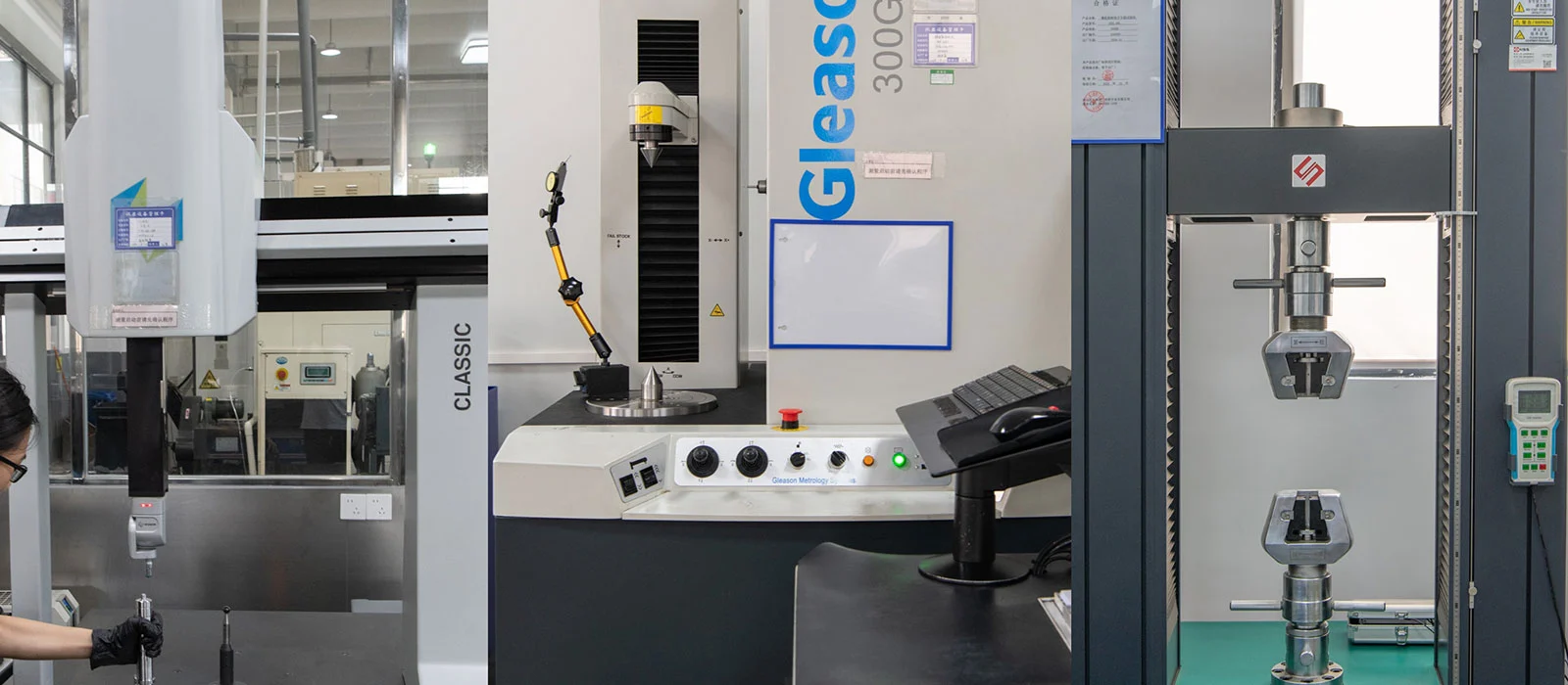
Inspection & Records CMM, runout and coaxiality measurement · material, heat-treatment and batch records Critical characteristics and the inspection scope follow the agreed project control plan.
Manufacturing & Inspection

How YUBAO Builds and Checks a Hollow Shaft

The process route is set around the features that must stay related after drilling, heat treatment and grinding. Inspection follows the same datum plan used to machine the part.

CNC machining of custom hollow shaft geometry
Manufacturing

Machining the bore and outside features

CNC turning establishes journals, shoulders and outside references. Deep-hole drilling or boring creates the internal geometry. Broaching and internal or external grinding are added where the drawing calls for them.

Turning · deep-hole drilling · boring · broaching · internal grinding · OD grinding
Inspection of hollow shaft bore and outside datum relationships
Quality Control

Inspection follows the same datum plan

Coaxiality, runout, fit bores, journals and shoulders are checked against the agreed references. Material, heat-treatment and inspection records can be carried into repeat production.

ISO 9001 · IATF 16949 · CMM inspection · batch traceability
Typical Applications

Where Hollow Shafts Work

YUBAO matches the bore, journals and interfaces to the duty shown in the drawing—from responsive automation to compact drives and special equipment.

Servo motor and industrial automation application using a precision hollow shaft
01

Servo Motors & Automation

For robotic and motion-control assemblies where response, runout and repeatability matter.

Reducer and electric drive application using a custom hollow shaft
02

Reducers & Electric Drives

For compact drive parts balancing torque, stiffness, concentricity and package size.

Machine tool and special equipment application using a custom hollow shaft
03

Machine Tools & Special Equipment

For spindle and actuator systems requiring coolant, drawbar or clamping passages.

FAQ

Before You Send a Hollow Shaft Drawing

Can YUBAO manufacture a hollow shaft directly from my drawing?

Yes. The quotation review considers the bore route, outside features, datum relationships, material, heat treatment, inspection scope and expected quantity before a process is confirmed.

What bore types can be reviewed?

Through bores, blind bores, stepped bores, internal keyways and other drawing-defined internal features can be reviewed. Feasibility depends on bore diameter, depth, access and tolerance.

How small can inner-to-outer coaxiality be controlled?

The current capability range includes projects targeting inner-to-outer coaxiality down to 0.03 mm. The achievable value depends on length, wall thickness, heat treatment and the selected datum and inspection method.

What information helps YUBAO prepare a useful quotation?

Send the 2D drawing and 3D model where available, together with torque, speed, duty cycle, material, treatment, critical datums, quantity, annual demand and any assembly or functional requirements.

Send Your Drawing.
Define the Right Manufacturing Route.

Share the application, critical dimensions, tolerances and expected annual volume. YUBAO will review the process route, inspection scope and project requirements before preparing the quotation. Drawing-based review · Project-specific process planning · Confidential drawing handling
Name*
Company Name
Email*
Country/Region
Product / Project Type
Quantity / Annual Volume
Upload Drawing
PDF, STEP, STP, DWG, DXF, IGES or ZIP
Project Requirements*
Verification Code*