
01
Keep the gear teeth related to the bore and mounting face
Tooth accuracy, bore fit, face runout, radial runout and mounting geometry are reviewed together so the finished gear works in the assembly rather than only on an inspection report.
A precision gear is more than a tooth form cut around a disc. The bore, gear teeth, face width, flange, hub, mounting holes and finished datums must work as one component. When those relationships are right, the gear locates cleanly, runs concentrically and transfers torque without asking the assembly to correct the part.
YUBAO manufactures made-to-print spur gears, helical gears, flange gears, compound gears and hardened gear discs for OEM drive systems. Gear hobbing, shaping, CNC turning, drilling, heat treatment, grinding and inspection are combined around the finished drawing—not around a fixed catalogue size.
Additional references: total thickness 5–200 mm, face width up to 150 mm, tooth hardness HRC 58–62 and core hardness HRC 30–45. Final capability depends on tooth geometry, material, heat-treatment movement, bore and flange structure, grinding access and inspection datum.

The gear structure should support the assembly, the process route and the final inspection plan at the same time. That means tooth geometry cannot be reviewed separately from the bore, mounting face, flange or heat-treatment route.
Tooth accuracy, bore fit, face runout, radial runout and mounting geometry are reviewed together so the finished gear works in the assembly rather than only on an inspection report.
A thin spur gear disc, a helical gear wheel, a flanged gear and an integral compound gear solve different packaging problems. The right structure can reduce adapters and accumulated assembly error.
Stock allowance, case depth, tooth hardness, core hardness and post-heat-treatment finishing must be planned before the first cut—not added after distortion appears.
Prototype and recurring OEM programs do not always need the same route. Blank preparation, turning, hobbing, shaping, drilling, grinding and inspection are selected around geometry, annual demand and project risk.
Choose the gear structure around torque transfer, mounting, noise, packaging, heat treatment and the inspection datums shown in the drawing.
Straight teeth make spur gears efficient, easy to inspect and well suited to parallel-shaft transmission. Bore fit, face width, tooth accuracy and runout remain tied to the finished datum structure.
Progressive tooth engagement can improve smoothness, load sharing and noise behavior. Normal module, helix angle, hand, face width and lead accuracy are reviewed together with the axial thrust carried by the assembly.
A flange gear integrates transmission with mounting or positioning. Gear teeth, flange diameter, flange thickness, pilot register, bolt circle and sealing face may all share one datum plan.
Two gear sections on one axis create compact ratio or timing functions. Tooth counts, modules, spacing, phase relationship and coaxiality determine whether the unit performs as intended.
Carburizing, nitriding or induction hardening may be followed by grinding, honing or other finishing where wear resistance, contact fatigue life or final tooth accuracy is critical.
These values support early drawing review. Blank fields in the special-parameter sheets remain drawing-defined until YUBAO confirms validated limits for the specific geometry and process.
| Parameter | Reference Capability | Tolerance / Grade | Engineering Relevance |
|---|---|---|---|
| Outside Diameter | Reference up to Ø200 mm | h11 reference | Tooth-tip diameter; final value follows the drawing. |
| Bore Diameter | Drawing-defined | H7 reference | Mating bore, datum axis and runout reference. |
| Total Thickness | 5–200 mm | ±0.05 reference | Includes gear body, flange and hub sections. |
| Module | 0.5–5.0 mm | Drawing-defined | Spur module or normal module for helical gears. |
| Pressure Angle | 15–30° | Drawing-defined | 20° is common; mating gear data must match. |
| Face Width | Reference up to 150 mm | Drawing-defined | Working tooth width and load distribution. |
| Accuracy Grade | DIN/ISO Grade 5 reference | Project-defined | Final grade depends on heat treatment and finishing. |
| Face Runout | Down to 0.02 mm | ≤ reference | Controlled relative to the bore datum. |
| Radial Runout | Down to 0.02 mm | ≤ reference | Tooth-tip circle relative to the bore datum. |
| Tooth Hardness | HRC 58–62 | Range | Typical hardened tooth surface. |
| Core Hardness | HRC 30–45 | Range | Supports toughness beneath the hardened layer. |
| Materials | Drawing-defined | — | Examples: 42CrMo, 20CrMnTi and 16MnCr5. |
| Heat Treatment | Tempering, carburizing, nitriding or induction hardening | Project-defined | Selected around wear, load, distortion and service life. |
| Static Balance | Drawing-defined | Project-defined | Important for larger or higher-speed gear discs. |
Open the relevant structure only when the project needs a deeper review of the features that control fit, phase, hardening or mounting.
| Control Item | Drawing Input | Status | Engineering Note |
|---|---|---|---|
| Normal Module | mn, mm | Drawing-defined | Must match the mating gear and applicable standard. |
| Helix Angle | β, degrees | Drawing-defined | Confirm direction, axial thrust and mating geometry. |
| Hand | Left-hand / right-hand | Required | Must match the paired gear and transmission layout. |
| Lead Deviation | Fβ, μm | Drawing-defined | Selected from final accuracy and face-width needs. |
| Control Item | Drawing Input | Status | Engineering Note |
|---|---|---|---|
| Flange OD / Thickness | Df / tf, mm | Drawing-defined | Controls mounting envelope and flange stiffness. |
| Pilot Register | Ds, mm | h6 / js6 reference | Locating diameter for repeatable assembly. |
| Bolt Circle | D1, mm | Drawing-defined | Include hole quantity and fastener specification. |
| Flange Face Finish | Ra, μm | Drawing-defined | Important where the face is used for sealing or locating. |
| Control Item | Drawing Input | Status | Engineering Note |
|---|---|---|---|
| Gear 1 / Gear 2 Data | z1, m1 / z2, m2 | Required | Tooth counts and modules may differ by function. |
| Section Spacing | c, mm | Drawing-defined | Controls packaging and cutter access. |
| Phase Accuracy | Degrees | Drawing-defined | Critical for timing or indexed transmission. |
| Coaxiality / Construction | Integral or assembled | Drawing-defined | Review assembly error, heat treatment and inspection access. |
| Control Item | Drawing Input | Status | Engineering Note |
|---|---|---|---|
| Pre-HT Accuracy | DIN / ISO | Drawing-defined | Usually lower than the finished accuracy target. |
| Heat-Treatment Route | Carburizing / nitriding / induction hardening | Required | Selected around material, load, wear and distortion. |
| Effective Case Depth | EHT, mm | Drawing-defined | Confirm minimum value and measurement method. |
| Post-HT Finishing | Grinding / honing / lapping | Project-defined | Corrects distortion and supports final tooth accuracy. |
The process route is built around the features that must remain related after tooth generation, heat treatment and final finishing.
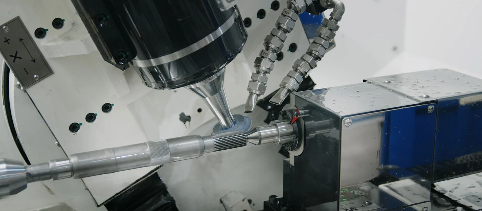
Blank preparation establishes material allowance. CNC turning creates the bore, faces, hub, flange and registers. Hobbing or shaping generates the tooth form; drilling and tapping complete mounting features. Heat treatment develops surface and core properties, followed by grinding, honing or other finishing where the drawing requires tighter control.
Inspection is not limited to tooth count and outside diameter. The relationship between the teeth, bore, face, flange, register and mounting pattern is checked so the part can be assembled and run from the same datum structure used during manufacturing.
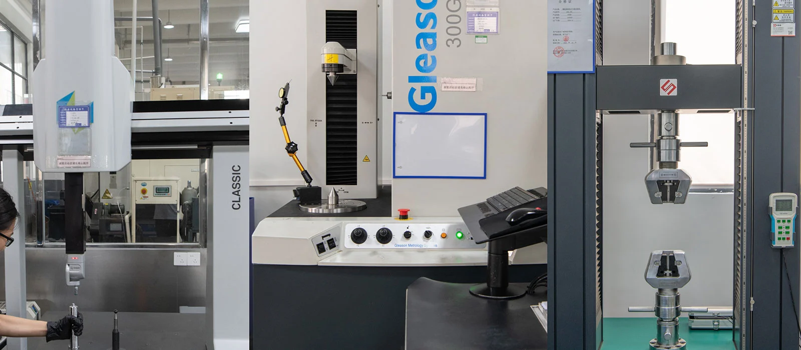
YUBAO reviews gear structure, material, heat treatment and inspection requirements around the load, operating environment and assembly shown in the customer drawing.
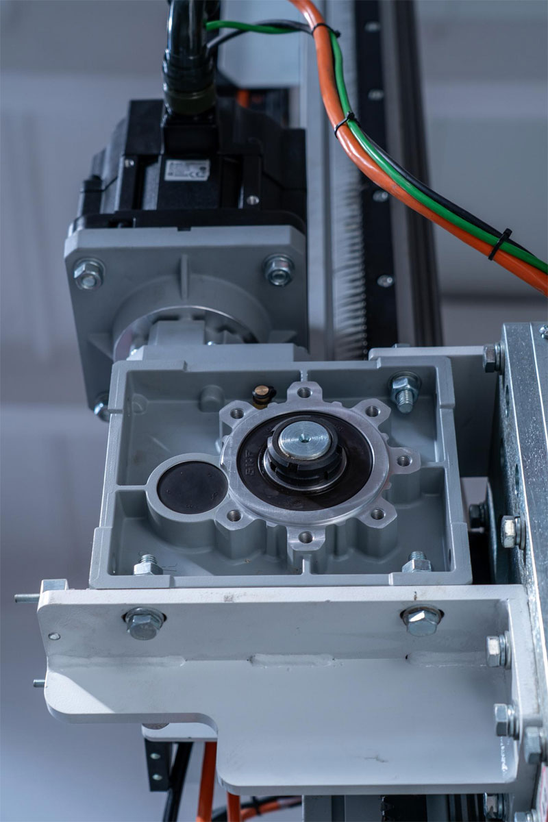
Spur, helical and compound gears where tooth accuracy, bore concentricity and repeatable assembly influence positioning.

Drawing-based gears for conveyors, lifting systems, electric drives and repeated-duty automation equipment.

Hardened or ground gears for headstocks, feed systems, indexing mechanisms and transmission assemblies.

Gear wheels and flange gears where smooth transmission, mounting accuracy and durable tooth surfaces support service life.

Compound, flanged and heat-treated gears for compact drive layouts, shifting systems and application-specific transmission.
Another product family may suit the assembly better when the torque path, axial layout, mating geometry or enclosure changes.


