

01
Motors, Reducers & Gearboxes
Bearing, spacer and locating sleeves where journal fit, component position, runout and repeatable installation must remain controlled.
A shaft sleeve may look simple, but its job is defined by the relationship between the bore, outside diameter, wall thickness, end face and the shaft or housing around it.
Depending on the application, the same basic component may be described as a bearing sleeve, wear sleeve, spacer sleeve or locating sleeve. YUBAO manufactures made-to-print shaft sleeves for motors, reducers, pumps, automation, material-handling systems and industrial machinery.
Reference values support early drawing review. Final fit, material, oil-groove geometry, hardness and inspection scope are confirmed against the released drawing and mating-part information.

A useful sleeve does more than fill a gap. Its bore, outside diameter, wall thickness, end face and lubrication path must work together after installation.
The fit, coaxiality, wall thickness and end-face relationship determine whether the sleeve runs true, supports the mating part and assembles without distortion.
A replaceable sleeve can provide a bearing seat, seal-running surface, wear layer, spacer or locating interface without forcing the main shaft to carry every service requirement.
Steel, alloy steel, bronze and cast-iron sleeves behave differently under load, wear, corrosion and lubrication. Oil-groove design is reviewed around motion and lubricant flow.
Reference ranges for early screening. Final capability depends on installed fit, material, wall design, lubrication, machining access and the datum structure defined in the drawing.
| Feature | Reference Capability | Engineering Relevance |
|---|---|---|
| Size Range | Bore Ø6–150 mm · OD Ø10–300 mm · length 5–200 mm | Overall feasibility depends on bore depth, wall thickness, diameter ratio, tooling access and required installed fit. |
| Fit & Geometry | H7 bore · h6–js6 OD reference · bore-to-OD coaxiality down to 0.01 mm | Bore, OD, wall thickness and end face must be reviewed together because installation can change the finished relationship. |
| Wall & End Face | Minimum wall thickness 2.0 mm · end-face perpendicularity down to 0.015 mm | Wall design must support machining, installation and service load without distortion or loss of roundness. |
| Surface & Lubrication | Bore and OD Ra 1.6 μm reference · straight groove, spiral groove or no groove | Surface condition and groove design follow bearing, sealing, wear and lubricant-path requirements. |
| Materials & Hardness | 42CrMo, 40Cr, bronze, cast iron and drawing-defined materials · hardness by duty | Material and hardness depend on load, wear, corrosion, lubrication and the mating component. |
Open a group only when the drawing needs a deeper fit, wall, lubrication or inspection review.
The process is planned around the relationships that remain important after installation—not around isolated free-state dimensions.

CNC turning establishes the outside diameter, shoulders and end faces. Precision boring, reaming and internal grinding control the bore, while external grinding finishes selected fit or wear surfaces.
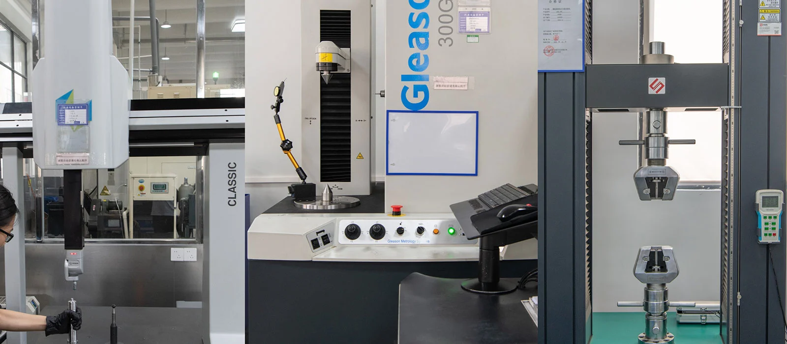
Inspection checks bore and OD size, coaxiality, wall thickness, length, end-face perpendicularity, surface finish and oil-groove geometry. Material, hardness and heat-treatment records follow the agreed project plan.
YUBAO matches the installed fit, material, lubrication and inspection plan to the load, motion and maintenance strategy shown in the drawing.
Bearing, spacer and locating sleeves where journal fit, component position, runout and repeatable installation must remain controlled.

Wear sleeves and running surfaces requiring replaceability, corrosion-aware materials or a defined lubrication path.

Drawing-based sleeves for rollers, actuators, lifting equipment and compact mechanisms requiring controlled support and alignment.
Another component route may suit the drawing better when weight, torque transfer, maintenance or assembly access changes.


Yes. YUBAO reviews the bore, outside diameter, wall thickness, material, mating-part tolerances, lubrication requirements and annual volume before confirming the manufacturing and inspection route.
YUBAO can review bearing sleeves, wear sleeves, spacer or distance sleeves, locating sleeves, oil-grooved sleeves and other drawing-defined cylindrical sleeve components.
The final fit is reviewed with the mating shaft or housing, material, heat treatment and installation method. Reference fits are applied only when they suit the finished assembly.
A finished drawing or 3D model, mating shaft and housing dimensions, required fits, material and hardness, oil-groove details, lubrication method, application, quantity and annual demand help YUBAO prepare a useful quotation.