

01
Spur Gear Shafts
Integrated straight-tooth and shaft structures for compact parallel-axis transmission stages.
A gear shaft is not simply a shaft with teeth cut on one end. The tooth form, bearing journals, shoulders, keyways, heat treatment and inspection datums have to work as one rotating component.
YUBAO manufactures drawing-based spur gear shafts, helical gear shafts, pinion shafts and selected internal-tooth gear shaft components for reducers, motors, automation, material-handling equipment and industrial machinery. CNC turning, gear hobbing, shaping, skiving, heat treatment, tooth grinding, journal grinding and inspection are selected around the finished geometry and production volume.
Reference data support early drawing review. Final capability depends on tooth count, shaft diameter, gear location, heat-treatment distortion, grinding access, datum structure and the inspection standard specified on the released drawing.

The gear and shaft cannot be reviewed as separate drawings when tooth contact, journal alignment and bearing support depend on one rotating geometry.
When the gear and shaft are manufactured as one component, the tooth position stays directly related to the journals that support rotation.
Profile, lead and pitch accuracy have to work with bearing seats, shoulders, end faces and a clear datum plan.
Spur, helical and internal-tooth structures use different combinations of hobbing, shaping, skiving, broaching, heat treatment and grinding.
Reference values for early screening. Final capability follows the released drawing, datum structure and named inspection standard.
| Feature | Reference Capability | Engineering Relevance |
|---|---|---|
| Gear Types | Spur, helical, pinion and selected internal-tooth gear shaft components | Tooth access, shaft geometry and datum relationships determine the manufacturing route. |
| Module & Pressure Angle | Module / normal module 0.5–3.0 mm · pressure angle 15°–30° | Tooth count, mating gear data and the applicable DIN, ISO or customer standard must be defined. |
| Helical Geometry | Helix angle up to 45° reference · left-hand or right-hand · face width up to 150 mm reference | Helix angle, hand, axial load, bearing arrangement and grinding access are reviewed together. |
| Accuracy & Surface | DIN / ISO Grade 6–7 reference · tooth surface Ra 0.4–1.6 μm reference | Profile, lead, pitch and runout requirements must be tied to a named standard and inspection method. |
| Heat Treatment | Tooth hardness 55–62 HRC · core hardness 30–45 HRC reference | Material, case depth, distortion allowance and post-treatment finishing are confirmed as one route. |
| Internal-Tooth Relationship | Bore H7–H9 reference · gear-to-bore coaxiality down to 0.02 mm reference | Internal teeth are reviewed with bore fit, tooth access and shaping, broaching or power skiving feasibility. |
The route is planned around the relationship between the gear teeth, bearing journals, shoulders, keyways, splines and mounting interfaces.

CNC turning establishes the shaft geometry first. Hobbing, shaping, broaching or skiving is selected by tooth form and access, followed by heat treatment and grinding where required.
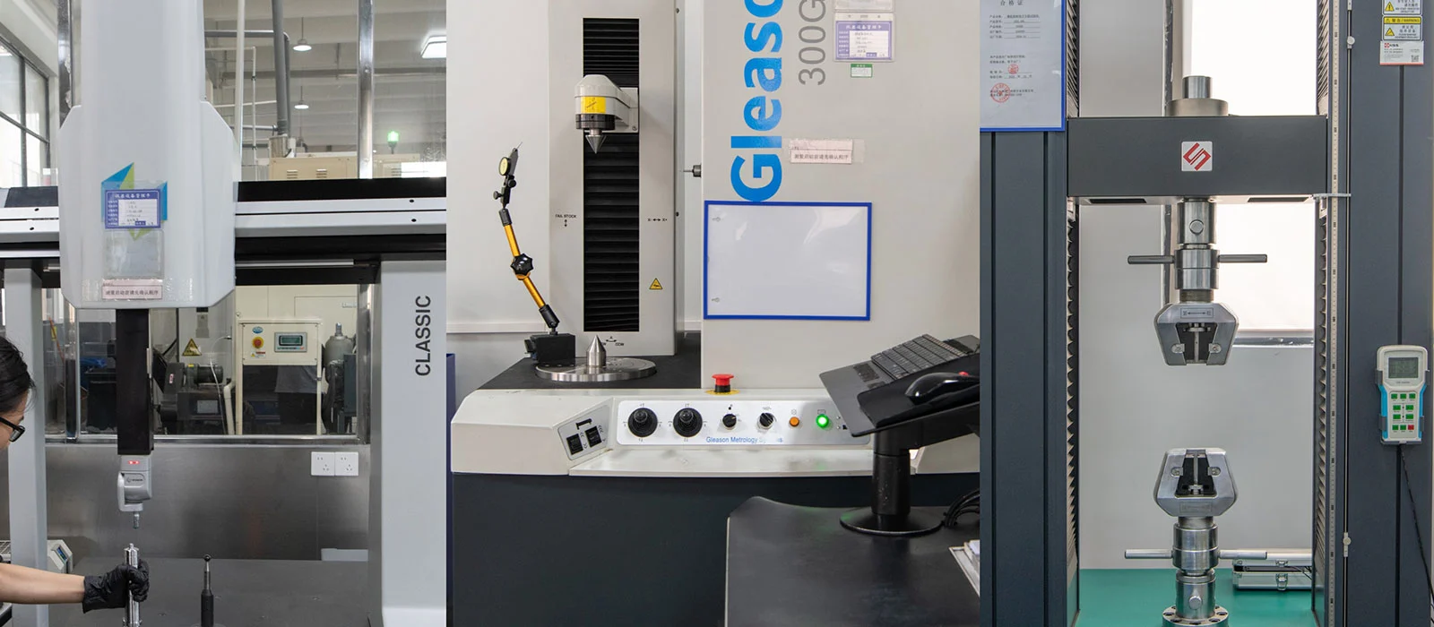
Inspection may cover profile, lead, pitch, tooth runout, gear-to-journal coaxiality, bearing seats, shoulders, hardness and traceability.
YUBAO reviews tooth geometry, shaft structure, heat treatment and inspection as one drawing-defined component.
Integrated straight-tooth and shaft structures for compact parallel-axis transmission stages.

Helical tooth forms for smoother engagement, reviewed with helix hand, axial load, bearing arrangement and speed.

Selected internal-tooth shaft or carrier-style components where bore fit, coaxiality and machining access are critical.
Tooth accuracy, journal alignment, torque, speed and duty cycle are matched to the actual drive system shown in the drawing.
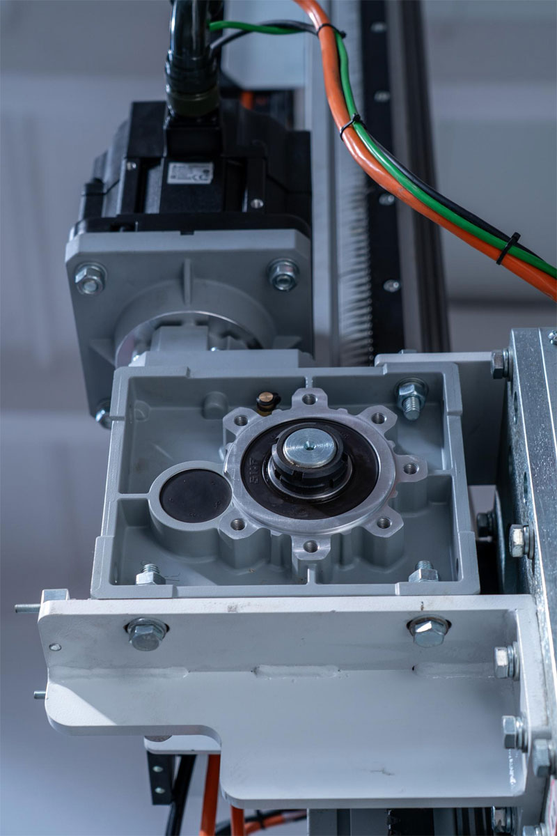
Integrated pinion and gear shafts for compact transmission stages.

Compact gear shafts for controlled-motion systems requiring stable positioning and low runout.
Durable drawing-based shafts where journals, keyways, splines and teeth operate as one component.
A one-piece gear shaft is one solution. Compare these related shaft options before the drawing is finalized for production.


Yes. YUBAO reviews the gear type, shaft geometry, material, heat treatment, accuracy requirements, application duty and production volume before confirming the manufacturing and inspection route.
YUBAO can review spur gear shafts, helical gear shafts, pinion shafts and selected internal-tooth gear shaft components. Final feasibility depends on tooth access, shaft geometry, hardness, required grade and measurement method.
Yes, when the drawing and geometry require it. Gear grinding and journal grinding can be planned around the functional datum relationship so the finished tooth position remains related to the bearing seats.
The drawing should define the applicable DIN, ISO or customer standard together with profile, lead, pitch, runout and shaft-datum requirements. YUBAO then confirms the available process and inspection route for those features.
Alloy and carburizing steels can be reviewed according to the drawing. Final material, case depth, tooth hardness, core hardness and post-heat-treatment finishing route are confirmed for the project rather than selected from a fixed catalogue.
A finished drawing or 3D model, gear standard, module, tooth count, pressure angle, helix angle and hand, material, heat treatment, datum requirements, tolerances, torque, speed, quantity and application information help YUBAO prepare a useful quotation.